Tag: 3D Vision; Date: 12 January 2020
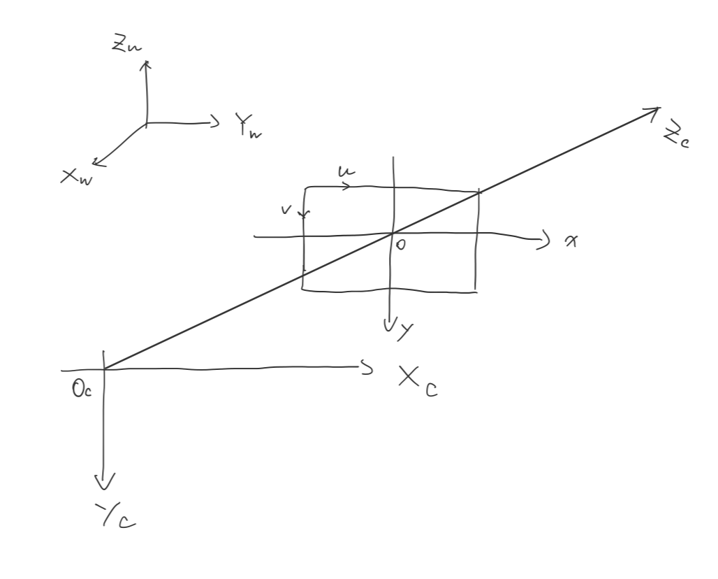
A typical camera model composed by following coordinate system:
When we take a picture using camera, the location of objects in Euclidean space being transform to the planar pixel location.
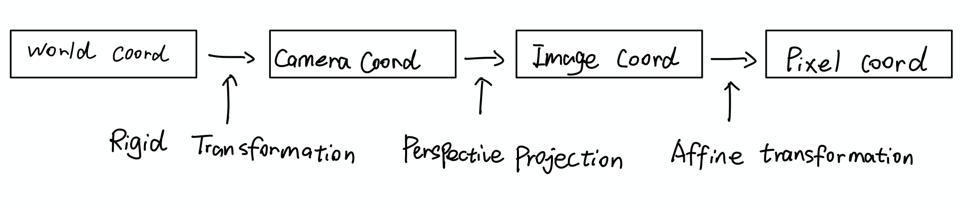
Rigid Transformation
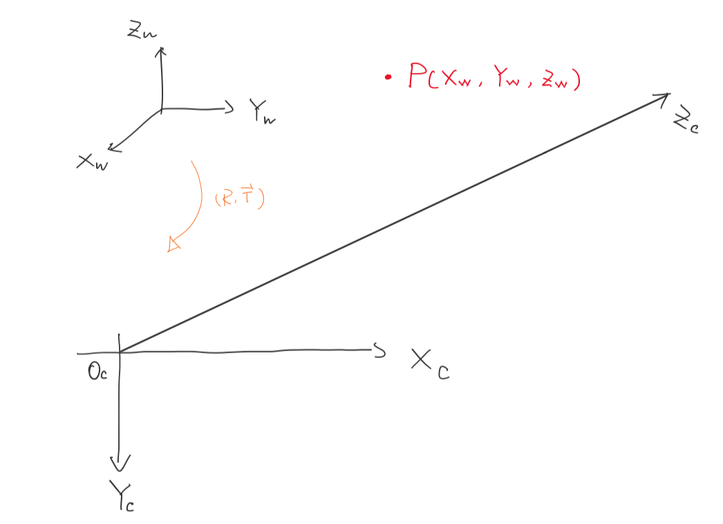
Let’s represent the position of a 3D point in world coordinate $P_W=\begin{bmatrix}
X_W
Y_W
Z_W
\end{bmatrix}$. The same point can also be expressed in camera coordinate $P_C = \begin{bmatrix}
X_C
Y_C
Z_C
\end{bmatrix}$, by using rigid transformation.
, where $R$ is a 3x3 matrix and $\vec{T}$ is a 3x1 vector.
We can also write like
\[\begin{bmatrix} X_C \\ Y_C \\ Z_C \\ 1 \\ \end{bmatrix} = \begin{bmatrix} R & \vec{T}\\ \vec{0} & 1\\ \end{bmatrix} \begin{bmatrix} X_W \\ Y_W \\ Z_W \\ 1 \\ \end{bmatrix}\]Perspective Projection
The point $P_C$ go through the lens and project point $p$ onto the sensor inside the camera:
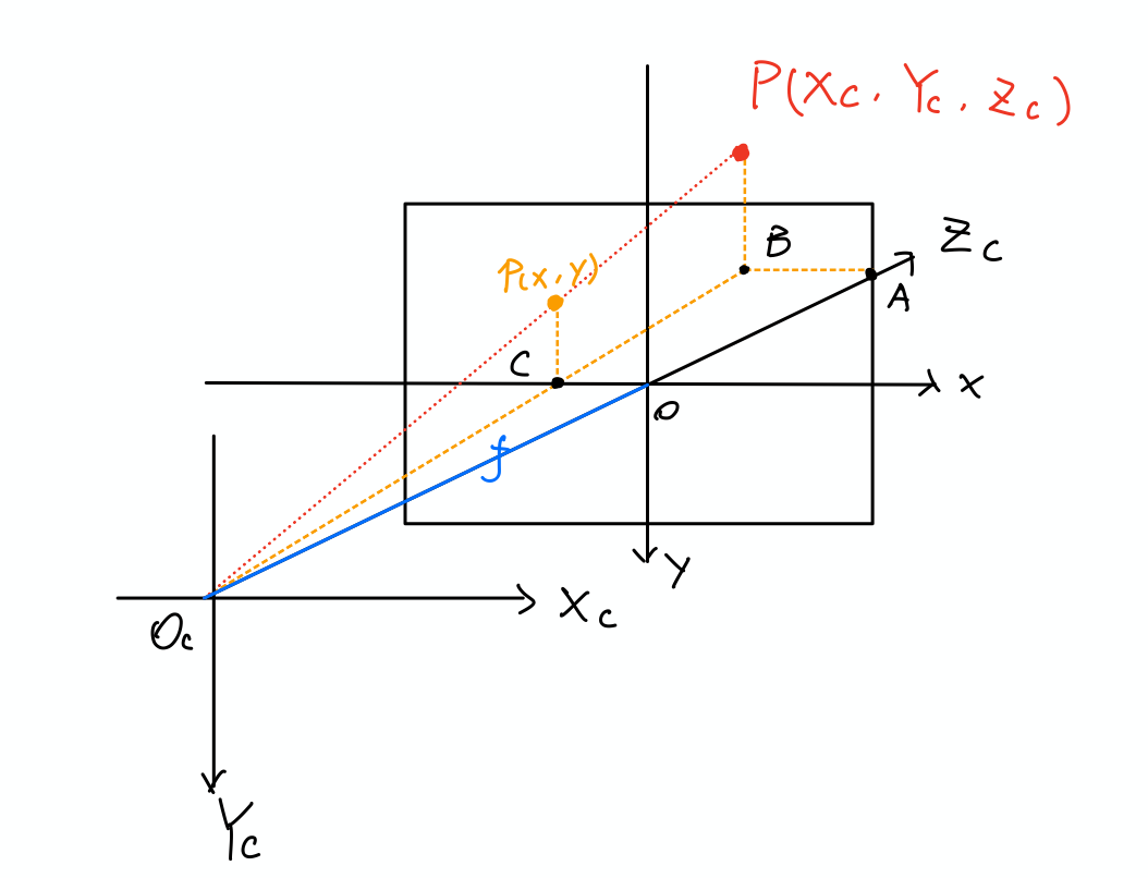
Because of the similar triangle
\[\frac{X_C}{x} = \frac{Y_C}{y}= \frac{Z_C}{f}\] \[x = f\frac{X_C}{Z_C}, y = f\frac{Y_C}{Z_C}\]where $f$ is the focal length. Now we can write the relation between the Image Coordinate with Camera Coordinate.
\[Z_C\begin{bmatrix} x \\ y \\ 1 \end{bmatrix} = \begin{bmatrix} f & 0 & 0 & 0 \\ 0 & f & 0 & 0 \\ 0 & 0 & 1 & 0 \\ \end{bmatrix} \begin{bmatrix} X_C \\ Y_C \\ Z_C \\ 1 \end{bmatrix}\]The $Z_C$ on the left side can be replace with scaling factor $s$, because this equation hold for any point on the projection line $\vec{pP}$.
\[s\begin{bmatrix} x \\ y \\ 1 \end{bmatrix} = \begin{bmatrix} f & 0 & 0 & 0 \\ 0 & f & 0 & 0 \\ 0 & 0 & 1 & 0 \\ \end{bmatrix} \begin{bmatrix} X_C \\ Y_C \\ Z_C \\ 1 \end{bmatrix}\]Given any point, we can now find the location of perspective projection of that point.
Affine Transformation
Physical length quantity → Pixel: After the point be projected onto sensor inside the camera, the camera generate a digital image of the point that composed by pixels.
The relation between Image Coordinate and Pixel Coordinate can be described by the Affine Transformation(scaling + shifting).
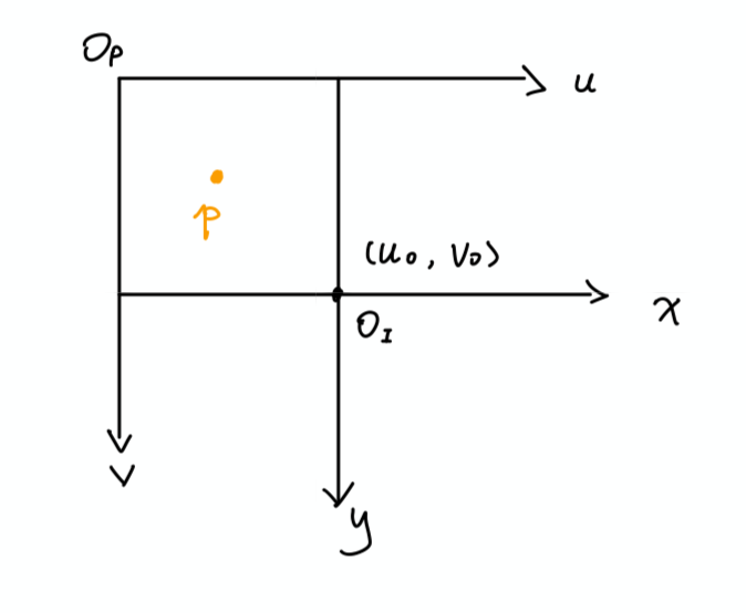
$dx, dy$: The physical quantity of one pixel(e.g. how long(mm/m/cm..) is a pixel).
$\frac{x}{dx}$: Turn the unit of physical quantity to unit of pixel.
Extrinsic parameters: represents a rigid transformation from 3-D world coordinate system to 3-D camera coordinate system
Intrinsic parameters: represents a projective transformation from 3-D camera’s coordinates into the 2-D image coordinates.
\[s \begin{bmatrix} u \\ v \\ 1 \end{bmatrix} = \underbrace{ \begin{bmatrix} \frac{1}{dx} & 0 & u_0\\ 0 & \frac{1}{dy} & v_0 \\ 0 & 0 & 1 \end{bmatrix} \begin{bmatrix} f & 0 & 0 & 0 \\ 0 & f & 0 & 0 \\ 0 & 0 & 1 & 0 \\ \end{bmatrix} }_\text{Intrinsics} \underbrace{ \begin{bmatrix} R & \vec{T}\\ \vec{0} & 1\\ \end{bmatrix} }_\text{Extrinsics} \begin{bmatrix} X_W \\ Y_W \\ Z_W \\ 1 \\ \end{bmatrix}\]